Sintered Wire Mesh

Custom Sintered Wire Mesh Filter Element

A sintered wire mesh element built to your drawing — cylinder, disc or custom shape — with the stack sized for the duty.

  • 1 – 200 μm
  • Multi-layer sintered wire mesh
  • up to ≤600 °C
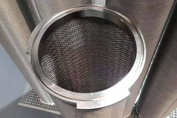
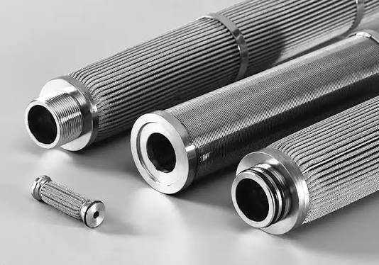
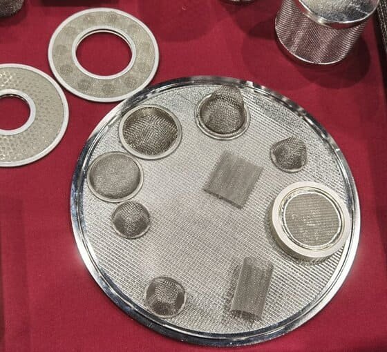
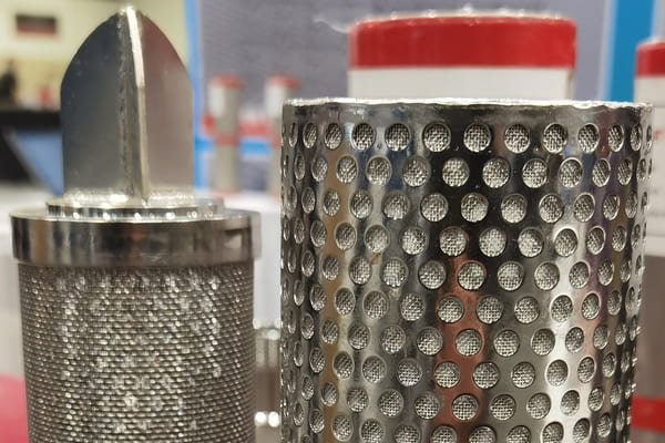
Sintered wire mesh filter element formed to a drawing, with welded support and connection detail

A sintered wire mesh element made to your drawing: a cylinder, a disc or a custom shape, with the layer stack chosen for the duty rather than the shape. Ratings 1–200 μm to 600 °C. Our engineers work from your drawing, OEM part number or a used element, and quote only after the drawing is approved.

When the element is not a catalogue shape, it is built to a drawing. A sintered wire mesh element can be a cylinder, a disc or a shape drawn for the housing, and the layer stack is chosen for the duty rather than for the shape. Ratings run from 1 to 200 μm, in liquid and gas service up to 600 °C. The element is sintered into one rigid sheet and then formed to the shape the drawing calls for, so the aperture is set before the geometry and does not change when the part is shaped.

About 70% of the elements we make are replacements, ordered against an OEM part number, a drawing or a used part. Where the shape is unusual, a used element is often the fastest route: we measure it, name the layer stack that reproduces its behaviour and match the connection detail. The remaining 30% start from operating conditions, and our application engineers design the element from them. A stepped cylinder, a disc and a shape drawn for the housing are all built from the same sintered sheet, so the material behaviour is known before the shape is new.

Designing from the duty needs seven inputs: temperature and peaks, the medium and its corrosive constituents, working pressure and differential pressure, the contaminant and its particle size distribution, the rating you need with any bubble point or air permeability target, the flow rate and the number of elements per housing, and the geometry or OEM part number. Send what you have; we ask for the rest.

The process is fixed: we confirm the element can be made, then issue a drawing with tolerances and connection details for your approval, and only then quote. Drawing review takes 3–5 working days, samples ship in 20–30 days and production runs take 30–60 days, from a minimum of a few pieces to a few dozen. Forming and welding happen in our plant, and every batch is measured for bubble point and air permeability.
Key Benefits

What this element buys you in service

  • 01

    The shape follows the housing

    Cylinder, disc or a custom shape: the element is formed after the sheet is sintered, so an unusual geometry does not force a compromise on the medium.

  • 02

    Sized from operating conditions

    Our application engineers work from temperature, medium, pressure and flow rather than from the nearest catalogue size.

  • 03

    Replacements matched to the part in service

    Send the OEM part number, the drawing or a used element and the equivalent is confirmed on dimensions, medium and connection.

  • 04

    Nothing is quoted before it is agreed

    Feasibility first, then a drawing with tolerances and connection details for your approval, and the price only after that.

Construction

How the element is built

  1. Protective layer

    A coarse woven mesh on the outside of the finished element, sized to the shape and to what the element is cleaned with.

  2. Control layer — the rated layer

    Sets the rating and the bubble point, chosen from the duty rather than from a catalogue size.

  3. Dispersion layer

    Spreads the flow across the rated layer in whatever geometry the drawing asks for.

  4. Support layers and connection

    Coarser layers carry the differential pressure, with the rim, flange or adapter welded in house after forming.

Protective layerFiltration layerrated, fine meshSupport layersrigid, backwashable
Section through the element wall Section through the element wall: a fine rated mesh between a protective layer and the rigid support layers that make the element backwashable.

Specification

Technical specifications

The figures we publish for this element. Where a duty needs something outside them, the review says so before a price is given.

Filtration rating 1 – 200 μm
Media Multi-layer sintered wire mesh
Form To drawing — cylinder, disc or custom shape
Alloys 304 · 316L · 310S · 904L · Hastelloy · Inconel · Monel · Ti · Ni
Maximum service temperature up to ≤600 °C
End connection Welded connection detail — rim, flange, adapter or support layer — to your drawing
Cleaning method Backwashable; cleaned in place or off-line
Batch test Bubble point and air permeability measured on every batch; the record travels with the dispatch
Structure Multi-layer sintered wire mesh, stack chosen for the duty
Geometry To drawing — cylinder, disc or custom shape
Rating 1–200 μm, set by the control layer
Welding TIG, resistance and laser welding of rims, flanges, adapters and support layers
Testing Bubble point and air permeability on every batch; ISO 9001

Materials

Alloys this element is built in

The alloy follows the medium, the temperature and what the element has to resist. Where a duty sits between two of them, an engineer says which one and why.

  • 304 stainless steel

    General industrial duty, where the drawing does not call for more.

  • 316L stainless steel

    Where chlorides or acids rule out 304.

  • 310S stainless steel

    Heat-resistant grade for continuous high-temperature service.

  • 904L stainless steel

    High-alloy austenitic grade for chlorides and acids.

  • Hastelloy

    Nickel alloy for aggressive media where stainless is not enough.

  • Inconel

    Nickel-chromium alloy for high temperature with corrosion.

  • Monel

    Nickel-copper alloy for chlorides and seawater duty.

  • Titanium

    Corrosive or high-purity service, including where low extractables matter.

  • Nickel alloys

    Aggressive media at temperature, where stainless is no longer enough.

Industries

Where this element runs

The duties this element is bought for, and what it is filtering in each of them.

  • Chemical fiber and polymer

    Spin packs and odd-shaped holders where no catalogue element fits.

  • Petrochemical

    Replacements against an OEM part number, where the connection detail has to match.

  • Hydrogen and industrial gas

    Elements designed from flow and pressure rather than from a size list.

  • Semiconductor and high-purity

    Parts built to a drawing where the batch record has to travel with the dispatch.

The industries page sets each of these duties in place, with the systems it belongs to and the filter positions we are asked to quote in it

Customisation

Built to your drawing

Everything is to your drawing: the shape, the layer stack, the rating, the alloy and the connection. Cylinder, disc or a custom shape, with the tolerances written on the drawing we send you for approval. Send the geometry, the OEM part number or a used element and the operating conditions behind it.

Send what you have — a drawing, a part number, a photograph of the element in place, or just the operating conditions. Nothing is quoted from a part number alone.

MOQ A few pieces to a few dozen
Sample lead time 20–30 days
Production lead time 30–60 days

Downloads

Datasheet, drawing and batch record

No document is published for this element yet. Ask for it and the engineering desk sends the drawing and the specification sheet — and, on a repeat order, the batch record with them.

Why Us

Tested before it ships, from a plant you can audit

Every element is welded and batch-tested in our own plant, and the batch record travels with the dispatch. About 70% of our work is a replacement for an element already in service, which is why a drawing or a used part is enough to start from.

  • ISO 9001 Quality system
  • 70 / 30 Replacement work to work designed from conditions
  • 30–40% Below the brand element it replaces
  • 3–5 days Drawing review before a quote

Questions

Questions this element raises

What do you need to design the element?

Seven inputs: temperature and peaks, the medium and its corrosive constituents, working pressure and differential pressure, the contaminant and its particle size distribution, the rating with any bubble point or air permeability target, the flow rate and elements per housing, and the geometry or OEM part number. Send what you have and we ask for the rest.

Can you copy an element we already use?

That is most of what we make. Send the OEM part number, the drawing or a used element and we confirm the equivalent on dimensions, medium, layer stack and connection detail before anything is quoted.

What shapes can be made?

Cylinder, disc or a custom shape. The sheet is sintered before it is formed, so the rating is set by the layer stack and is not affected by the shape.

How does the custom process run?

We confirm the element can be made, then issue a drawing with tolerances and connection details for your approval, and quote after that. Nothing is made before the drawing is agreed.

Who reads the drawing?

Our application engineers — fifteen of them work on drawings and operating conditions, and they are the ones who name the layer stack and the alloy.

What is the minimum and the lead time?

A few pieces to a few dozen elements. Drawing review takes 3–5 working days, samples ship in 20–30 days and production runs take 30–60 days, and the batch record travels with the dispatch.

Send the drawing, or the duty.

A drawing, an OEM number or a used element is the fastest route to a quote. With only the process — temperature, medium, pressure, flow — our engineers select the medium and issue a drawing for approval before anything is sampled.

Replacement elements cost 30–40% less than the brand they replace · Samples ship in 20–30 days